

-
-
mi sono ispirato da questa guida [External Link Removed for Guests] e lo adattata con il D1 Mini / D1 Mini Pro
Io avevo tempo fa acquistato questi Moduli Wi-Fi da Integrare in H.A. ma è molto complesso e macchinoso ed ero in cerca di una soluzione più semplice.
- -
Materiale Necessario
Spinotto connettore JST 2.54 a 4 pin - [External Link Removed for Guests] / [External Link Removed for Guests]
D1 Mini / D1 Mini Pro - [External Link Removed for Guests] / [External Link Removed for Guests]
Spinotti Cavi Dupont - [External Link Removed for Guests] / [External Link Removed for Guests]
DD4012SA 1A DC 5-40V a 3.3V - [External Link Removed for Guests]
Resistori 100 Ohm - [External Link Removed for Guests] / [External Link Removed for Guests]
Pin Header maschio 90 gradi - [External Link Removed for Guests] / [External Link Removed for Guests]
Cavo Cellulare Usb - Micro USB ( Solo prima Programmazione )
Stagnatore e Stagno
Colla a Caldo
Case ( scatoletta )
un pò di pasienza e buona Manualità
Progettto
- -
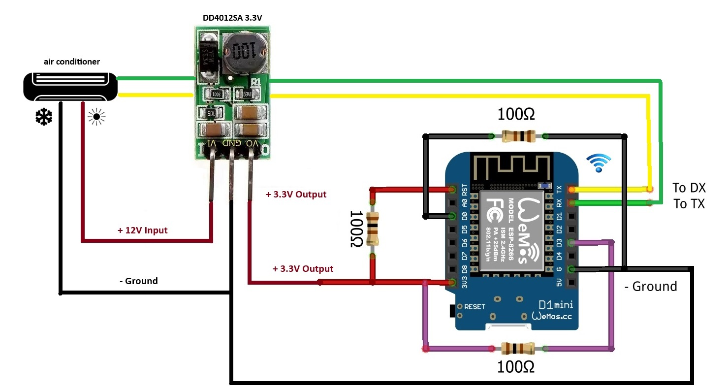
Dal condizionatore individuate il +12V / Neutro / TX / RX aiutandovi con un Tester e segnatevi i colori e posizioni , ci sarà pure un 4.8 - 5 V che non ci servirà.
Con lo spinotto JST 2.54 a 4 pin ed gli Spinotti Cavi Dupont tramite i colori e posizioni createvi il cavo che va al condizionatore stagnando il tutto insieme con i Resistori 100 Ohm , non stagateli direttamente alla board perchè i Resistori 100 Ohm non vi faranno programmare la board D1 Mini, quindi preferisco che siano rimovibili ( che si possono togliere e rimettere all'occorenza.
Prendete i Pin Header maschio 90 gradi e stagnateli sulla Board D1 Mini ( utilizzate solo i 7 punti che vi servono )
dopopassiamo alla programmazione
andate su "Home Assistant" nel menù selezionate "ESPHome" in basso a destra selezionate "New Device"
nella schermata seguente vi chiede se volete aprire "ESPHOME Web" oppure continuare cliccate su "Continue"
date un nome al vostro progetto io in questo caso ho messo "Porta-Casa" cliccate su "Next"
levate la spunta su "Use Reccomended Settings" e scegliete "ESP8266" e cliccate su "Next"
- -
nel menù scrollate fino che non vedete "WeMos D1 Mini Pro" selezionatelo e poi cliccate su "Next"
- -
nella schermata successiva cliccate sulla chiave che vi comparirà a schermi e vedrete la scritta "Copied" a questo punto cliccate su "Skip"
- -
a questo punto vedrete che a creato il vostro progetto adesso passiamo alla configurazione finale clicchiamo su "EDIT"
cambiate la Board con questa dicitura
alla prima riga sopra tutto lo script fino alla dicitura API - *potete modificare le diciture "cond-sogg & Cond-Sogg" a vostro piacimento per riconoscere il vostro condizionatore*
Codice: [Local Link Removed for Guests]
# External Components
external_components:
  - source:
      type: git
      url: https://github.com/GrKoR/esphome_aux_ac_component

# Name
esphome:
  name: cond-sogg
  friendly_name: Cond-Sogg

# Board Tipe
esp8266:
  board: d1_mini

# Enable logging
logger:
  level: DEBUG
baud_rate: 0Codice: [Local Link Removed for Guests]
# Web Server
web_server:
  port: 80
  auth:
    username: !secret web_server_user
password: !secret web_server_passwordCodice: [Local Link Removed for Guests]
# Wi-Fi
wifi:
  ssid: !secret wifi_ssid
  password: !secret wifi_password

  # Enable fallback hotspot (captive portal) in case wifi connection fails
  ap:
    ssid: [color=#FF0000]"Cond-Sogg"[/color]
password: !secret ap_passwordCodice: [Local Link Removed for Guests]
# MQTT Configuration
mqtt:
  broker: !secret ip_broker
  username: !secret mqtt_username
password: !secret mqtt_passwordCodice: [Local Link Removed for Guests]
captive_portal:
debug:

uart:
  id: ac_uart_bus
  # ATTENTION! For TX and RX use GPIO4 (D2) and GPIO5 (D1) for NodeMCU-like boards!
  # See docs for details: https://github.com/GrKoR/esphome_aux_ac_component/blob/master/docs/HARDWARE-EN.md
  tx_pin: GPIO1
  rx_pin: GPIO3
  baud_rate: 4800
  data_bits: 8
  parity: EVEN
  stop_bits: 1

# Wifi Sensor Signal
sensor:
  - platform: wifi_signal
    name: WiFi Signal
    update_interval: 120s
    unit_of_measurement: "dBa"
    accuracy_decimals: 0

# Led Blue Onboard ON ( false ) / OFF ( true )
status_led:
  pin:
    number: D4
    inverted: false

# Climate Setting
climate:
  - platform: aux_ac
    # Enter Name
    name: "Cond. Sogg."
    id: aux_id
    uart_id: ac_uart_bus
    period: 7s
    display_inverted: false
    timeout: 300
    optimistic: true
    indoor_ambient_temperature:
      name: AC Indoor Ambient Temperature
      id: ac_indoor_ambient_temp
      accuracy_decimals: 1
      internal: false
    outdoor_ambient_temperature:
      name: AC Outdoor Ambient Temperature
      id: ac_outdoor_ambient_temp
      internal: false
    outdoor_condenser_temperature:
      name: AC Outdoor Condenser Temperature
      id: ac_outdoor_condenser_temp
      internal: false
    compressor_suction_temperature:
      name: AC Compressor Suction Temperature
      id: ac_compressor_suction_temp
      internal: false
    indoor_coil_temperature:
      name: AC Indoor Coil Temperature
      id: ac_indoor_coil_temp
      internal: false
    compressor_discharge_temperature:
      name: AC Compressor Discharge Temperature
      id: ac_compressor_discharge_temp
      internal: false
    defrost_temperature:
      name: AC Defrost Temperature
      id: ac_defrost_temp
      internal: false
    display_state:
      name: AC Display State
      id: ac_display_state
      internal: false
    defrost_state:
      name: AC Defrost State
      id: ac_defrost_state
      internal: false
    inverter_power:
      name: AC Inverter Power
      id: ac_inverter_power
      internal: false
    inverter_power_limit_value:
      name: AC Inverter Power Limit Value
      id: ac_inverter_power_limit_value
      internal: false
    inverter_power_limit_state:
      name: AC Inverter Power Limit State
      id: ac_inverter_power_limit_state
      internal: false
    preset_reporter:
      name: AC Preset Reporter
      id: ac_preset_reporter
      internal: false
    vlouver_state:
      name: AC Vertical Louvers State
      id: ac_vlouver_state
      internal: false
    visual:
      min_temperature: 16
      max_temperature: 32
      temperature_step: 1
    supported_modes:
      - HEAT_COOL
      - COOL
      - HEAT
      - DRY
      - FAN_ONLY
    custom_fan_modes:
      - MUTE
      - TURBO
    supported_presets:
      - SLEEP
    custom_presets:
      - CLEAN
      - HEALTH
      - ANTIFUNGUS
    supported_swing_modes:
      - VERTICAL
      - HORIZONTAL
- BOTHecco tutto il codice , fate attenzione a non sovrascrivere il codice API e quello OTA
Codice: [Local Link Removed for Guests]
# External Components
external_components:
  - source:
      type: git
      url: https://github.com/GrKoR/esphome_aux_ac_component

# Name
esphome:
  name: condizionatore-c-p
  friendly_name: Condizionatore-C-P

# Board Tipe
esp8266:
  board: d1_mini

# Enable logging
logger:
  level: DEBUG
  baud_rate: 0

# Enable Home Assistant API
api:
  encryption:
    key: "nK+MIFD7ZBdxChbHSQImn43Cx1/uZIdjk9fKYG1bcBE="

# Ota Password
ota:
  password: "a32d95e188bb425a9d2ee8dee11939dc"

# Web Server
web_server:
  port: 80
  auth:
    username: !secret web_server_user
    password: !secret web_server_password

# Wi-Fi
wifi:
  ssid: !secret wifi_ssid
  password: !secret wifi_password

  # Enable fallback hotspot (captive portal) in case wifi connection fails
  ap:
    ssid: "Condizionatore-C-P"
    password: !secret ap_password

# MQTT Configuration
mqtt:
  broker: !secret ip_broker
  username: !secret mqtt_username
  password: !secret mqtt_password

captive_portal:
debug:

uart:
  id: ac_uart_bus
  # ATTENTION! For TX and RX use GPIO4 (D2) and GPIO5 (D1) for NodeMCU-like boards!
  # See docs for details: https://github.com/GrKoR/esphome_aux_ac_component/blob/master/docs/HARDWARE-EN.md
  tx_pin: GPIO1
  rx_pin: GPIO3
  baud_rate: 4800
  data_bits: 8
  parity: EVEN
  stop_bits: 1

# Wifi Sensor Signal
sensor:
  - platform: wifi_signal
    name: WiFi Signal
    update_interval: 120s
    unit_of_measurement: "dBa"
    accuracy_decimals: 0

# Led Blue Onboard ON ( false ) / OFF ( true )
status_led:
  pin:
    number: D4
    inverted: false

# Climate Setting
climate:
  - platform: aux_ac
    # Enter Name
    name: "Cond. Cam. P."
    id: aux_id
    uart_id: ac_uart_bus
    period: 7s
    display_inverted: false
    timeout: 300
    optimistic: true
    indoor_ambient_temperature:
      name: AC Indoor Ambient Temperature
      id: ac_indoor_ambient_temp
      accuracy_decimals: 1
      internal: false
    outdoor_ambient_temperature:
      name: AC Outdoor Ambient Temperature
      id: ac_outdoor_ambient_temp
      internal: false
    outdoor_condenser_temperature:
      name: AC Outdoor Condenser Temperature
      id: ac_outdoor_condenser_temp
      internal: false
    compressor_suction_temperature:
      name: AC Compressor Suction Temperature
      id: ac_compressor_suction_temp
      internal: false
    indoor_coil_temperature:
      name: AC Indoor Coil Temperature
      id: ac_indoor_coil_temp
      internal: false
    compressor_discharge_temperature:
      name: AC Compressor Discharge Temperature
      id: ac_compressor_discharge_temp
      internal: false
    defrost_temperature:
      name: AC Defrost Temperature
      id: ac_defrost_temp
      internal: false
    display_state:
      name: AC Display State
      id: ac_display_state
      internal: false
    defrost_state:
      name: AC Defrost State
      id: ac_defrost_state
      internal: false
    inverter_power:
      name: AC Inverter Power
      id: ac_inverter_power
      internal: false
    inverter_power_limit_value:
      name: AC Inverter Power Limit Value
      id: ac_inverter_power_limit_value
      internal: false
    inverter_power_limit_state:
      name: AC Inverter Power Limit State
      id: ac_inverter_power_limit_state
      internal: false
    preset_reporter:
      name: AC Preset Reporter
      id: ac_preset_reporter
      internal: false
    vlouver_state:
      name: AC Vertical Louvers State
      id: ac_vlouver_state
      internal: false
    visual:
      min_temperature: 16
      max_temperature: 32
      temperature_step: 1
    supported_modes:
      - HEAT_COOL
      - COOL
      - HEAT
      - DRY
      - FAN_ONLY
    custom_fan_modes:
      - MUTE
      - TURBO
    supported_presets:
      - SLEEP
    custom_presets:
      - CLEAN
      - HEALTH
      - ANTIFUNGUS
    supported_swing_modes:
      - VERTICAL
      - HORIZONTAL
- BOTHnon modificate le porte GPIO o D1/D2 ecc sennò non funzionerà il D1 Mini come controller ci ho impiegato 3 settimane a trovare quelle adatte dal progetto originale.
io come Case ho utilizzato il case originale del vecchio Controller Wi-Fi , più avanti creerò un file per la stampa 3D
ed ecco come si vede sulla Plancia
-